
An advanced electronics repair course can combine circuit troubleshooting, soldering, diagnostics, and electrical fundamentals with online learning. The course described here includes 10 hours of on-demand video across 10 sections and 51 lectures, plus 4 articles and 2 downloadable resources. It covers practical topics such as testing components, tracing circuit faults, and understanding voltage, current, and resistance.
Choosing training that connects electrical principles to hands-on repair tasks makes sense: technicians need to understand both how a circuit should work and how to find the fault when it doesn’t. Online certificate programs can also include analog and digital circuits, circuit analysis, circuit design, soldering, and fabrication techniques.
This guide explains what course content to look for, how troubleshooting and soldering skills fit together, and what online certificate options may involve. You’ll get a clear picture of the learning path, from core electrical concepts to component-level diagnostics, so you can judge which training fits your goals.
Key Takeaways
- Learn a step-by-step approach to testing transistors and tracing faults, including how a Zener diode behaves in a circuit.
- See how basic soldering, advanced component work, and microsoldering fit into a technician’s repair skills.
- Use a structured diagnostic process to narrow down faults even when a schematic isn’t available.
- Connect voltage, current, and resistance through practical circuit examples, including an LED current-limiting calculation.
- Compare online certificate programs by their circuit topics, hands-on techniques, study format, and common admission requirements.
Transistor testing and circuit troubleshooting
Build troubleshooting skills by following a circuit from input to output. A useful lesson connects transistor tests, component behavior, and board-level symptoms instead of treating each part in isolation.
Transistor Testing and Circuit Faults
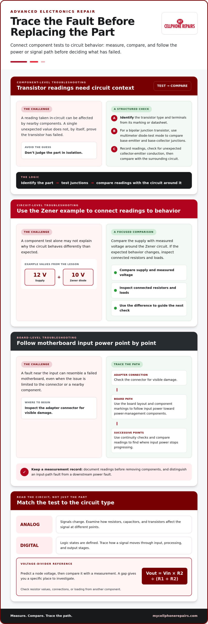
Start by identifying the transistor type and its terminals from its marking or datasheet. For a bipolar junction transistor, a multimeter’s diode-test mode can help compare the base-emitter and base-collector junctions. Record the readings, then check for unexpected conduction between collector and emitter. In-circuit readings can be affected by nearby components, so compare them with the surrounding circuit before deciding the transistor has failed.
Next, trace the circuit’s signal or supply path. A course example uses a 12 V supply and a 10 V Zener diode. Compare the supply and the measured voltage around the Zener circuit, then inspect connected resistors and loads if the expected behavior changes. This links a component test to a circuit-level fault instead of replacing parts by guesswork.
Motherboard Power-Input Repairs
Laptop motherboard power-input repair begins by tracing the path from the adapter connection toward the board’s power-management components. Check the connector for visible damage, then follow the circuit to identify where input power stops progressing. A fault near the input can resemble a failed motherboard, even when the issue is limited to a connector or nearby component.
Use the board layout, component markings, and continuity checks to narrow the search. Compare readings at successive points rather than probing randomly. A repair lesson should explain how to distinguish a damaged input path from a downstream power fault, and how to document each measurement before removing components.
Component Analysis Across Circuit Types
Analog circuits handle changing signals, so examine how resistors, capacitors, and transistors affect signals at different points. Digital circuits use defined logic states, so trace how a signal moves between input, processing, and output stages. In both cases, connect each component’s role to the symptom instead of memorizing isolated part names.
Look for training that progresses from reading a schematic to testing a physical board. This makes it easier to connect a component’s expected function with its measured behavior, whether the circuit carries an audio signal or a digital control signal.
Circuit analysis also supports design decisions. For a voltage divider, calculate the output by multiplying the input voltage by R2, then dividing by the sum of R1 and R2. Use that relationship to predict a node’s voltage and compare it with a measurement. A gap between prediction and measurement gives you a specific place to investigate, including resistor values, connections, or loading from another component.
Are there financial aid options, employer reimbursement, or payment plans for electronics repair courses? These are separate funding routes: financial aid depends on program eligibility, employer reimbursement follows workplace policies, and payment plans depend on the course provider’s terms. Review each option before enrolling so you understand how the course will be paid for.
What safety rules and risks should students know when repairing electronic devices? Disconnect power before inspecting a board, and handle batteries and charged components carefully. Use appropriate eye protection and tools, keep the work area clear, and don’t probe an energized circuit unless you’re trained to do so. Stop if a component is damaged or the repair requires handling you haven’t learned.
Basic, advanced, and microsoldering techniques
Repair skills progress from clean through-hole joints to precise work on compact circuit boards. A strong lesson demonstrates the method, tool, and inspection step for each repair.
Basic soldering starts with preparing the joint, heating the pad and lead, then feeding solder into the connection. Inspect the finished joint for a secure bond and unwanted bridges to nearby pads. Practice on a spare board first to build control before working around delicate components.
Advanced techniques involve removing and replacing surface-mount parts without damaging nearby pads. Microsoldering goes further, using magnification and a fine soldering tip to work on small board-level connections. For example, a technician might remove a damaged connector, clean its pads, align the replacement, and inspect each joint before testing the board.
Choose lessons that explain temperature control, tip selection, component alignment, and cleanup. A useful exercise compares a well-formed joint with a cold joint or solder bridge. Students should also learn to secure the board and prevent nearby components from shifting during rework.
What prerequisites or experience are required for advanced electronics repair training? Certificate-program admission commonly calls for a high school diploma or GED. Some programs describe a 2.0 or higher high school GPA as a common requirement, and many require at least one advanced mathematics course.
What tools and equipment are needed for advanced electronics repair training? Start with a soldering iron, multimeter, precision tweezers, and a board holder. Microsoldering practice also benefits from magnification and fine tips, since small pads and closely spaced components require careful placement.
Repair technicians diagnose faults, replace components, maintain equipment, and follow safety and quality standards. For example, a repair might involve replacing a damaged connector, then checking continuity and function before returning the device to use. Clear notes help track symptoms, measurements, parts replaced, and test results.
Pay depends on the role and work setting. Electronics repair specialists in the United States earned a median salary of $53,900 in 2014. That historical figure gives context, not a current salary estimate. Repair work can involve consumer devices, commercial equipment, or industrial systems, each with different tasks and skill demands.
Build practice around a repeatable sequence: inspect the board, identify the joint or component, make the repair, then test the result. If you want to see how repair work applies to real devices, explore phone and computer repair examples.
Advanced electronics diagnostics without schematics
Without a schematic, diagnose the board as a physical map. Use connector labels, component markings, visible traces, and measurements to build a working picture. A laptop board’s charging connector, for example, provides a clear starting point. Record what you see before removing components or applying power.
Begin with the reported symptom, then inspect the device and board for clues. A no-power complaint differs from a device that starts but loses function during use. Look for damaged connectors, corrosion, cracked components, lifted pads, and signs of previous repair. Photograph both sides of the board so you can compare the original layout after disassembly.
Next, identify major landmarks. Look up component markings in manufacturer datasheets, and note connector names printed on the board. A part marked “U” commonly refers to an integrated circuit, while “R” often identifies a resistor. Treat these markings as clues, not proof. Confirm each part’s role through its datasheet, nearby connections, and measured behavior.
- Disconnect external power and document the device’s symptom.
- Inspect connectors, board edges, and visibly damaged areas.
- Identify ground points and trace connections from the affected port.
- Measure related components and record each reading with its location.
- Compare the results with datasheets or a working equivalent circuit.
Ground can provide a reference for measurements. Find a known ground point, then use continuity checks to map connections between the input, nearby components, and other board areas. A charging fault, for example, may lead from the port to a fuse, protection component, or power-management area. Let the board layout and readings guide the next test.
Compare matching channels when the board has repeated circuits. A stereo audio board may have left and right signal paths with similar components. If one side works and the other fails, compare corresponding points across both paths. Differences can narrow the fault area without a complete circuit diagram.
Use measurements to test a hypothesis, not to collect readings at random. If a device’s display stays dark while other functions operate, trace the display connector and surrounding components. Check for physical damage first, then compare relevant connections and component readings with datasheets. Change one variable at a time, and record what changed.
Thermal clues can also guide inspection. A component that becomes unusually warm may indicate a short or excessive load, but temperature alone cannot identify the failed part. Compare the symptom, board layout, and electrical readings before replacing anything. Recheck the circuit after each repair step, then test the original function and nearby functions.
Keep a simple diagnostic record with the symptom, board location, measurement, and result. A note such as “charging input, connector to protection component, continuity absent” is more useful than “board bad.” That record clarifies the next troubleshooting step and helps prevent repeated tests or unnecessary component removal.
Electricity, voltage, current, and resistance
Read a circuit by connecting voltage, current, and resistance to measurable behavior. Voltage is the electrical potential difference between two points. Current is the flow through a path, while resistance opposes that flow. Ohm’s law links them: voltage equals current multiplied by resistance. If a resistor measures 1,000 ohms and carries 0.01 amperes, its voltage drop is 10 volts.
Use units carefully. A multimeter may show volts, milliamps, or kilo-ohms, and confusing those prefixes changes the calculation. For example, 10 milliamps equals 0.01 amperes. Write down the value and unit together before applying a formula. Then compare the calculated result with the circuit’s expected behavior.
An LED current-limiting example makes the relationship practical. A 5 V supply, 3 V LED, and 10 mA current call for a 200 Ω resistor. The resistor takes the remaining 2 V, while the chosen current determines its value. This calculation helps explain why a resistor protects an LED from excessive current.
Measurements also depend on where and how you place the meter probes. To measure voltage, connect probes across the two points being compared. To measure resistance, isolate the part from the powered circuit and avoid paths that can distort the reading. A resistor labeled 1 kΩ should be interpreted alongside its circuit position and nearby components.
Current measurement requires a different setup. The meter must be in series with the path being measured, so current flows through it. Placing it across a supply as if measuring voltage can create a short. Practice on a simple battery, resistor, and LED circuit first, with the circuit unpowered during setup.
Voltage dividers show how resistance controls a circuit node. Their output depends on the input voltage and the two resistor values, with R2 positioned in the output calculation. For example, increasing R2 relative to R1 raises the output share. Predict the node voltage, then measure across the same points and compare.
When readings differ from the expected value, check the measurement setup before suspecting a component. Confirm the meter mode, probe contact, and selected circuit points. Then inspect connections and component values. A loose probe on a resistor can produce an unstable reading, while an incorrect meter range can obscure small changes.
Build a repeatable practice routine: sketch a simple circuit, calculate an expected voltage or current, measure it, and record the result with units. Repeat with a different resistor value, then explain how the change affects the LED or output node. This turns formulas into practical diagnostic tools rather than rules to memorize.
Online electronics repair certificate programs
Online study can cover circuit theory and repair methods without requiring every lesson to take place in a classroom. Compare the curriculum, pace, admission criteria, and certificate type before choosing a program.
Online Certificate Program Format
Electronics repair certificate programs commonly cover analog and digital circuits, circuit analysis, and circuit design. Some also teach soldering and fabrication techniques. Look for a clear connection between each topic and a practical task, such as diagnosing a faulty signal path or planning a circuit layout.
Online delivery doesn’t automatically mean every activity happens remotely. Distinguish video lessons from practical exercises, and note which tasks require electronic components or tools. A useful curriculum progresses from circuit concepts to guided repair work, then asks learners to apply those concepts to a new example.
Admission requirements vary by program. Common criteria include a high school diploma or GED. Some programs describe a high school GPA of 2.0 or higher as a common requirement, and many require at least one advanced mathematics course. Review these entry criteria alongside the course topics.
Course Costs
That figure applies to that course listing, not to every electronics repair certificate program. Certificate-program costs depend on the institution, curriculum, and included instruction, so compare what each program teaches before weighing the price.
Check whether the course offers focused lessons or a broader certificate curriculum. Compare its circuit topics, soldering instruction, and learning materials with your goals. A low price alone doesn’t show whether a course covers the depth of diagnostics or repair practice you need.
Course Length and Schedules
Online electronics repair certificate programs can typically be completed in less than one year. The actual pace depends on the program structure and how much study time you can set aside. Check whether lessons have fixed deadlines or allow flexible progress, then compare that format with your work and practice schedule.
Make a simple study plan before enrolling. Set regular time for lessons, circuit exercises, and reviewing difficult concepts such as analog signal behavior. Also check how the program organizes assignments and assessments. A schedule that leaves time to repeat practical exercises can help turn course material into usable repair skills.
For a focused choice, match the certificate curriculum to the tasks you want to learn. A learner aiming to analyze circuits should prioritize circuit analysis and design. Someone building board-repair skills should look for soldering and fabrication practice. Compare these details with program length and format, then choose the path that fits your learning needs.
My Cellphone Repairs: Samsung Phone Repair
My Cellphone Repairs offers Samsung Phone Repair when a device needs hands-on troubleshooting beyond course practice. Training can help you understand how circuits work, but a damaged phone still needs careful inspection to identify the cause and appropriate repair.
Turn to a repair technician when a Samsung phone has a fault you can’t safely diagnose or resolve. The same practical support is available for iPhone Screen Repair, MacBook Repair, and Battery Replacement. These services address specific device problems, while repair training builds broader technical knowledge.
For a device that needs professional attention, contact My Cellphone Repairs about Samsung Phone Repair.
Turn Your Repair Skills Into Your Next Step
Training is most useful when you keep applying it to real repair decisions. Choose a learning path that fits the devices and circuit work you want to handle, then build a habit of documenting symptoms, testing carefully, and reviewing each result. An advanced electronics repair course can strengthen that foundation, while practical experience helps you recognize when a problem needs hands-on attention.
For device repairs, My Cellphone Repairs offers Samsung Phone Repair, iPhone Screen Repair, and MacBook Repair. These services provide a practical option when a device needs repair rather than more study or troubleshooting at home. Use your new knowledge to guide your next repair decision, and choose professional service when it’s the right fit.
Contact My Cellphone Repairs to discuss a device repair. Keep learning, practice with care, and take the next step with confidence.
Frequently Asked Questions
What’s included?
The course listing includes on-demand video, articles, and downloadable resources. Use the articles to review key concepts, then apply the downloadable materials while working through a circuit example. Before enrolling, compare the lesson sequence with your learning goals: a beginner may prioritize electrical fundamentals, while a technician developing board-level skills may focus on diagnostics and soldering practice.
What topics are covered in an advanced electronics repair course?
Topics can include transistor testing, component-level troubleshooting, analog and digital circuits, circuit analysis, and design. Repair-focused lessons may also cover soldering and fabrication techniques. For a practical example, look for content that connects a measured voltage or failed component with a device symptom. That connection helps turn theory into a repeatable diagnostic process rather than a list of terms.
Which schools or providers offer advanced electronics repair courses in the United States?
My Cellphone Repairs offers a Technician Training Program with instruction in mobile-device hardware components and diagnostic techniques. For learners in Towson or Bowie, this is a local training option to consider. Other certificate programs may be offered through educational institutions, but compare each curriculum’s circuit topics, practical work, and certificate type before choosing a program.
Are advanced electronics repair courses available online, in person, or in hybrid formats?
Online certificate programs are available, and their schedules can suit learners who need flexibility. In-person and hybrid formats may also be available, depending on the program. Online lessons can build theory, while hands-on practice develops tool control and inspection habits. Compare how each format supports practical exercises, instructor feedback, and time to repeat a difficult repair task.
Do advanced electronics repair courses provide certificates or recognized credentials?
Some programs are designed as certificate programs, but a completion certificate and a recognized professional credential are not automatically the same. Check who issues the certificate and what it represents: course completion, demonstrated skills, or an external qualification. Also compare the stated learning outcomes with the repair work you want to pursue, such as diagnostics, component replacement, or soldering.
What jobs and salary ranges can graduates pursue after an advanced electronics repair course?
Possible work includes repairing, installing, and maintaining electronic systems in homes, businesses, and industrial settings. Some technicians work on vehicle electronics, while others service commercial or industrial equipment. The available salary figure is historical: electronics repair specialists in the United States earned a median salary of $53,900 in 2014. It is not a current salary range, and earnings vary by role and work setting.